Ceiling Fans with Lights Safety Checklist
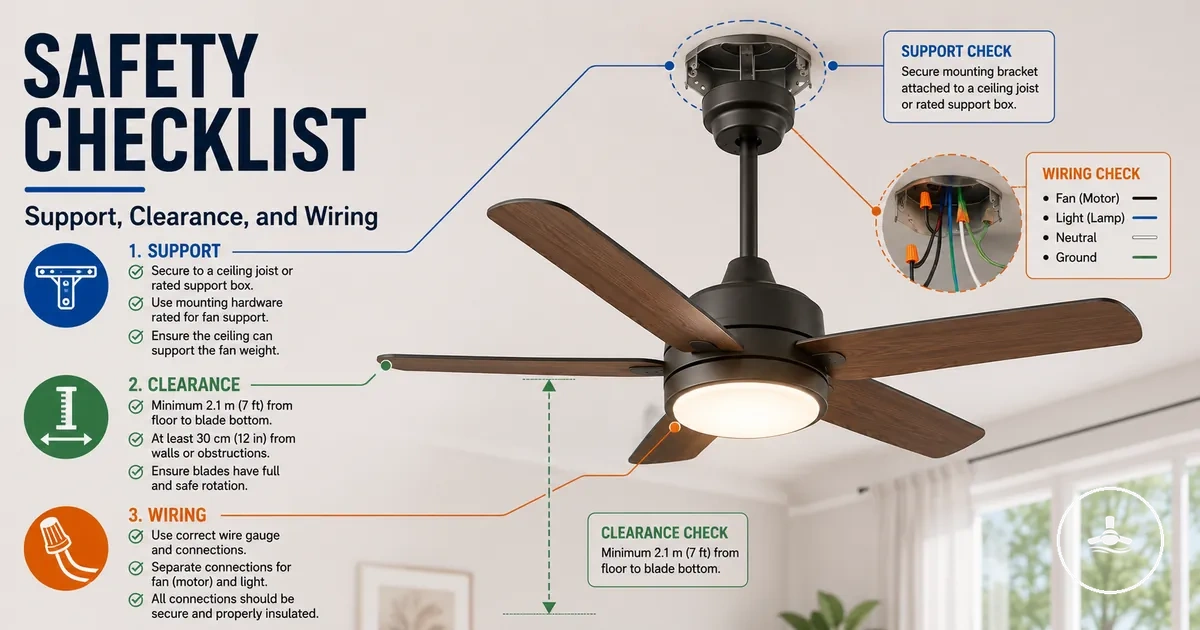
A ceiling fans with lights safety checklist refers to a structured set of safety checks used to assess support, clearance, wiring, light kit condition, and movement stability before normal use of a ceiling fan with light system. It focuses on identifying visible risks and inspection points rather than installation instructions. This scope separates safety checking from full installation procedures and keeps attention on potential hazards. It also ensures that the fan with light is evaluated as a combined system rather than isolated parts. The ceiling fans with lights context remains central when interpreting these safety conditions.
A homeowner or renter typically uses a safety checklist when a ceiling fan with light is already installed or when a new fixture is being evaluated before activation. In these situations, attention is usually placed on how the support structure holds the unit, whether blade clearance is sufficient for the room layout, and whether wiring connections appear stable and protected. The light kit also introduces additional inspection concerns such as heat exposure or loose covers. Movement behaviour such as wobble during operation can also indicate underlying mounting or balance issues. Together, these factors frame the main safety risk areas: support, clearance, wiring, and movement.
A ceiling fans with lights safety checklist provides a way to organize these inspection points into clear safety categories. It helps separate visible condition checks from issues that may require deeper verification, especially where hidden structural or electrical conditions cannot be confirmed visually. In many cases, uncertainty around wiring or mounting integrity may require review by a qualified electrician or reference to manufacturer instructions before continued use. This structured approach supports safer decision-making without assuming that visual inspection alone confirms full safety.
Each item in the checklist should be read as a condition-based indicator rather than a guarantee of safety or failure. Support, clearance, wiring, light kit condition, and wobble are evaluated as individual risk signals that may vary depending on the ceiling type, fan model, and installation environment. The checklist is intended to guide observation and highlight potential issues that need further attention, not to replace professional assessment or confirm installation quality.
Safety limits before installation or inspection
A safety checklist for ceiling fans with lights can flag visible risks and surface condition concerns, but it cannot confirm hidden wiring integrity or ceiling structure safety. It works only within visual check boundaries and does not certify internal support or electrical safety conditions. Any uncertainty about concealed components or mounting reliability requires a licensed electrician or qualified inspection rather than checklist confirmation.
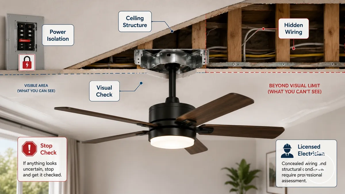
Safety limits before installation or inspection depend heavily on power isolation and visible-condition checks that can be safely observed without contact with live systems. Visual inspection may include external mounting condition, canopy stability, and apparent damage, but it does not extend to hidden wiring or internal ceiling structure verification. If any live wire exposure, unstable mounting, or unclear electrical state is suspected, stop checking immediately to reduce risk of contact with unsafe conditions.
Uncertain ceilings, damaged mounts, or unclear wiring conditions create scenarios where a ceiling fan with light cannot be evaluated safely through visual checks alone. In these cases, the safety limit shifts from observation to professional-only assessment to avoid misinterpretation of structural or electrical risk. These installation limits define when installation limits and qualified inspection boundaries must be considered before further action.
Caution: Safety limits before installation or inspection clarify when visual checks are no longer sufficient. This helps distinguish observation from professional intervention needs.
- Stop checking if live wiring or exposed electrical elements are suspected
- Do not proceed with contact when ceiling structure stability is unclear
- Avoid further inspection if mounting damage or looseness is visible
- Rely on a licensed electrician when hidden wiring conditions cannot be verified
- Follow manufacturer instructions when system limits are unclear
Fan-rated support and mounting checks
Fan-rated support and mounting checks for a ceiling fan with light refer to verifying whether the ceiling box, brace, and mounting assembly are designed to handle both the weight and movement of the unit. A ceiling fan with light requires fan-rated support and a secure mounting assembly, because appearance alone does not confirm structural suitability. The key safety factor is whether the support system is rated and properly fixed, not how stable it looks from the outside.
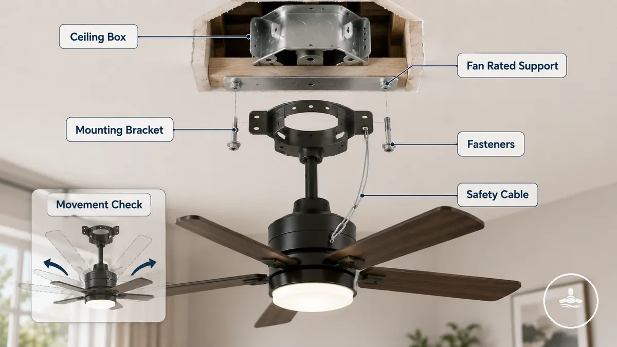
Support safety depends on how the mounting assembly distributes weight and resists movement during operation. A ceiling box or brace that is not fan-rated may not handle dynamic load from rotation, which can increase stress on fasteners and attachment points. The mounting bracket, fasteners, and safety cable all contribute to stabilizing the system, and weak connection points may lead to increased movement or long-term instability. These checks follow an EAV logic where each component is evaluated by rating, condition, and attachment reliability.
Older ceiling boxes or replacement light fixture points can create uncertainty because they may not clearly indicate whether they are designed for fan-rated support. In such cases, the mounting condition may look acceptable but still lack the structural rating needed for a ceiling fan with light. This uncertainty typically requires verification against manufacturer instructions or qualified assessment when the support type cannot be confirmed visually.
Before reviewing detailed components, the safety checklist focuses on whether support and mounting conditions indicate stable, fan-rated installation readiness or potential risk requiring further inspection.
Mini-checklist: Fan-rated support and mounting verification focuses on structural readiness before use.
- Ceiling box → fan-rated label or documentation → confirms support confidence or requires verification
- Mounting brace → presence and fixed condition → reduces risk of structural movement
- Mounting bracket → tight attachment → ensures stable connection to ceiling support
- Fasteners → secure and intact → prevents loosening under operational movement
- Safety cable → properly attached → provides additional retention support in case of stress
Support box rating and ceiling brace condition
The support box and ceiling brace condition determine whether a ceiling fan with light can be safely supported under load and movement, based on whether the support box has a fan rating and whether the ceiling brace provides stable structural attachment. A support box without a confirmed fan rating or a brace with weak fixation may not safely handle rotational movement or weight. Safety depends on verified rating and structural condition rather than surface appearance alone.
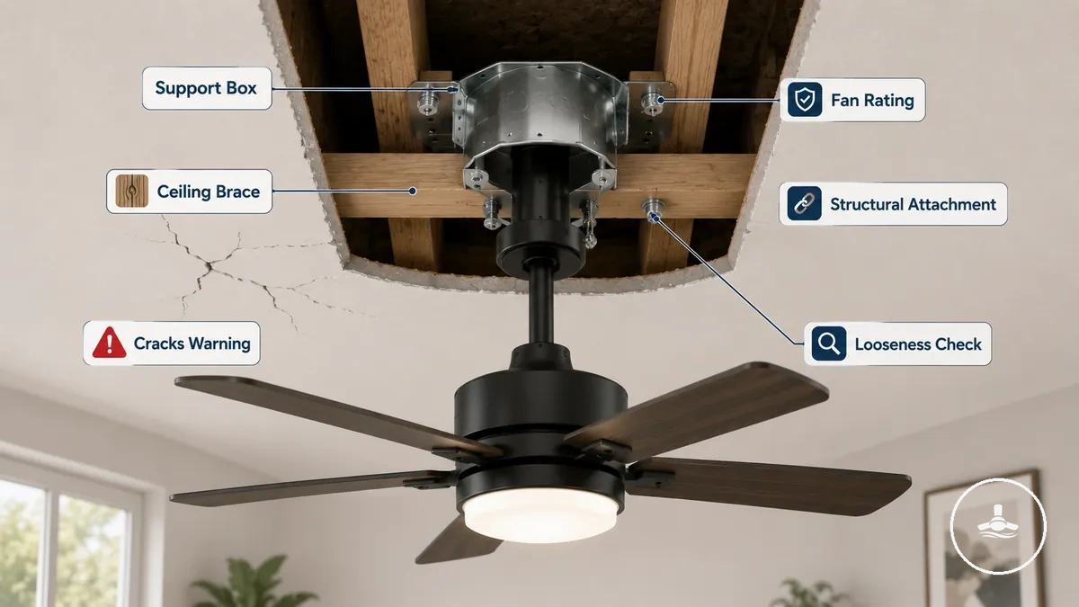
When a support box lacks clear fan rating documentation or the ceiling brace shows instability, the system may not provide reliable load distribution during fan operation. Visible cracks, looseness, or uncertain structural attachment can indicate reduced safety performance under weight and movement stress. In such cases, the condition must be treated as uncertain rating or compromised attachment, requiring professional verification before use. The checklist below confirms whether the support box rating and ceiling brace condition indicate safe structural attachment or require verification.
- Support box → fan rating confirmed → suitable for fan load conditions
- Support box → unknown rating → requires professional verification
- Ceiling brace → secure structural attachment → supports stable operation
- Ceiling brace → visible cracks → indicates structural weakness
- Ceiling brace → looseness detected → increases movement risk under load
Mounting bracket, fasteners, and safety cable fit
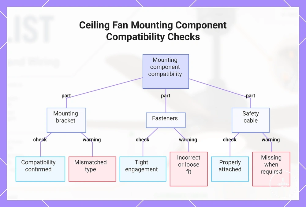
The mounting bracket, fasteners, and safety cable must match the ceiling fan with light and its attachment point requirements to maintain stable mounting under movement. Mounting bracket compatibility, fasteners such as screws or bolts, and safety cable inclusion are determined by manufacturer requirements rather than general interchangeability. Safe attachment depends on correct compatibility and tight engagement, not on assuming hardware can be freely substituted.
When mounting bracket fit is uncertain or fasteners and safety cable are missing or mismatched, the stability of the entire mounting system can become unreliable under fan rotation. Mismatched parts may reduce tight engagement or weaken attachment at critical points, increasing movement risk. In such cases, continued use should not proceed until compatibility is confirmed through manufacturer guidance or professional verification.
Key checks focus on whether each mounting component matches the required fit and condition before operation.
- Mounting bracket → compatibility confirmed → ensures correct attachment alignment with fan system
- Fasteners (screws/bolts) → tight engagement → reduces loosening and movement under rotation
- Safety cable → properly attached (if provided) → supports secondary retention under load
- Mounting bracket → mismatched type → increases instability and requires stop-check
- Fasteners → incorrect or loose fit → increases vibration and movement risk
- Safety cable → missing when required → requires verification before safe use
This chart shows the three mounting components (bracket, fasteners, safety cable) and the key checks and warnings to ensure stable ceiling fan installation.
Weight support and movement resistance
Weight support and movement resistance define separate safety criteria for a ceiling fan with light by separating static weight from dynamic movement. Static weight refers to the combined load of the fan body and light kit resting on the mounting system, while dynamic movement refers to operating forces created during rotation and vibration. These two conditions create different risk profiles, and combined risk increases when both load and movement act on the mounting surface.
When repeated wobble occurs during operation, it may indicate reduced movement resistance even if static weight appears properly supported. Mounting surface rigidity can influence how vibration is absorbed or transferred, which affects overall stability under operating movement. In such cases, wobble becomes an inspection trigger because it signals potential instability during use rather than during static conditions.
| Criterion | What to check | What it may indicate |
|---|---|---|
| Static weight | Fan body and light kit load | Baseline load support condition |
| Movement resistance | Operating rotation and vibration | Dynamic stability under use |
| Repeated wobble | Ongoing vibration during operation | Inspection trigger for instability |
Blade clearance and low ceiling safety checks
Blade clearance depends on ceiling height, blade sweep, mounting type, and nearby objects that may enter the operating space of a ceiling fan with light. Safe operating space is defined by blade distance from the floor (floor clearance), walls, doors, furniture, and beds during rotation. Because these factors change with room layout, blade clearance must be treated as a conditional safety check rather than a fixed fit outcome.
Low ceiling or tight room layouts can reduce headroom and side clearance, increasing sensitivity to mounting type and blade sweep. In these situations, contact risk may rise when furniture, beds, or doors sit within the clearance zone of the rotating blades. Low ceiling safety checks therefore depend more on room layout and object placement than on the visual appearance of the fan installation alone.
When clearance is marginal, small differences in mounting type or ceiling height may affect whether safe operating space is maintained. In such cases, reassessing the configuration may be necessary because limited headroom or side clearance can increase contact risk during operation. This boundary is clarified through low ceiling clearance considerations rather than assuming standard clearance is sufficient.
Blade clearance checklist:
| Clearance area | What to check | Safety concern | When to reconsider |
|---|---|---|---|
| Floor / headroom | Blade distance from floor during rotation | Reduced headroom increases contact risk | When clearance feels tight under operation |
| Walls / doors | Blade sweep proximity to vertical surfaces | Side contact during movement | When swing path approaches openings |
| Furniture / beds | Objects within rotation zone | Interference with moving blades | When objects sit under sweep path |
| Mounting type | Flush, standard, or extended drop position | Affects overall clearance profile | When mounting height limits spacing |
Floor clearance and headroom risk
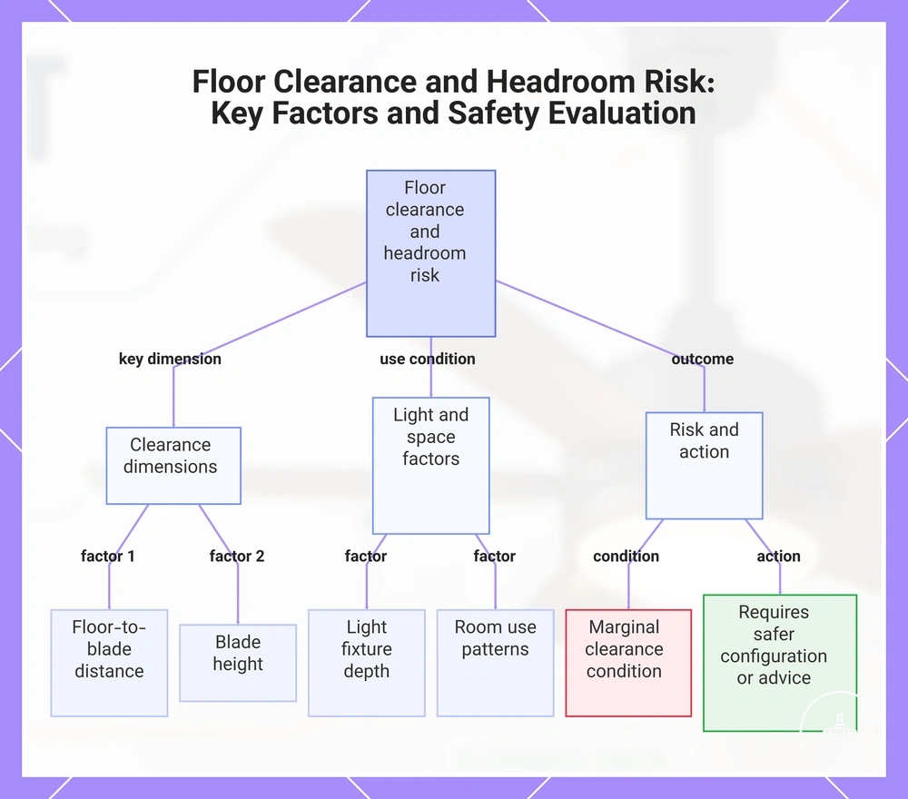
Floor clearance and headroom risk depends on floor-to-blade distance, blade height, light depth, and room use in a ceiling fan with light setup. Lower floor clearance reduces usable headroom and increases contact risk when people move beneath the fan. Light depth can also reduce perceived headroom even when blade height appears sufficient. These conditions must be evaluated as marginal clearance scenarios rather than fixed safety outcomes.
In walkways, bedrooms, or areas with raised-arm activity, headroom becomes more sensitive to blade height and room use patterns. Frequent movement under the fan can increase exposure to contact risk, especially when furniture placement or walking paths reduce safe spacing. In such environments, clearance assessment must account for how the space is actually used rather than static measurements alone. Where marginal clearance is present, safer configuration or professional advice may be required.
Vertical clearance checklist: Floor-to-blade clearance clarifies headroom safety based on room conditions.
- Floor clearance → reduced distance to blades → increased contact risk during movement
- Blade height → low mounting position → limited usable headroom in active spaces
- Light depth → extended fixture drop → reduced perceived overhead clearance
- Room use → high activity zones → higher likelihood of passing under blades
- Marginal clearance → tight vertical spacing → requires reassessment of setup safety
This chart outlines the main factors affecting floor clearance and headroom risk in ceiling fans with lights, including dimensions, room use, and required safety actions.
Wall, furniture, door, and bunk bed clearance
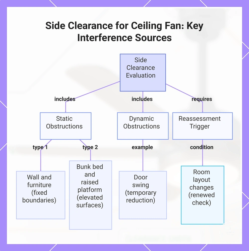
Side clearance for a ceiling fan with light depends on wall clearance, blade sweep, door swing, furniture placement, bunk bed position, and raised platform proximity. These elements can sit within or move into the blade sweep zone, increasing contact risk when room layout is tight or changes over time. Side clearance must therefore be evaluated as object-interference with the blade path rather than simple room spacing.
In spaces with opening doors, tall furniture, or bunk beds, blade sweep interactions can change during normal room use. A door swing may temporarily reduce wall clearance, while furniture height or a raised platform can bring surfaces closer to blade movement. When room layout is adjusted or objects are moved, clearance conditions should be reassessed to maintain consistent safety assumptions. This is especially relevant in shared or frequently rearranged rooms.
- Wall clearance → fixed boundary near blade sweep → increased risk if spacing is limited
- Door swing → moving obstruction → may enter blade path during opening and closing
- Furniture → tall or nearby objects → potential proximity to rotating blades
- Bunk bed → elevated sleeping area → increased user proximity to blade height zone
- Raised platform → elevated surface → closer interaction with overhead blade sweep
- Room layout changes → repositioned objects → require renewed clearance check
This chart shows the main object-interference sources and conditions that affect side clearance for a ceiling fan with light.
Flush mount and downrod clearance conditions
Flush mount and downrod clearance conditions depend on how mounting type changes blade height, ceiling distance, and overall room clearance. Flush mount reduces blade height by positioning the fan closer to the ceiling, while downrod increases the drop and shifts blade position lower into the room. These differences directly affect clearance behaviour and must be assessed based on ceiling height and room constraints rather than assuming a universal fit.
Flush mount creates reduced drop with tighter ceiling distance, which can limit clearance in low ceiling conditions, while downrod adjusts blade height downward to improve positioning in higher ceiling spaces but may reduce headroom clearance depending on installation. In sloped ceiling or vaulted ceiling environments, mounting alignment may require a mounting kit to maintain correct angle and stable clearance. This relationship is clarified through sloped ceiling mounting considerations when ceiling geometry affects installation conditions.
| Mounting condition | What changes | Clearance risk | When to verify |
|---|---|---|---|
| Flush mount | Reduced blade drop and closer ceiling position | Tighter ceiling spacing in low ceiling setups | When ceiling height limits usable clearance |
| Downrod | Increased blade drop via rod length adjustment | Lower blade height may affect headroom clearance | When room height or obstacle proximity varies |
| Sloped or vaulted ceiling | Angled mounting alignment with adjustment kit | Alignment changes may affect clearance consistency | When ceiling angle requires structural adaptation |
Wiring and light electrical safety checks
Wiring safety refers to electrical safety checks that identify visible risks and uncertainty in a ceiling fan with light system, focusing on power isolation, connection condition, and exposed conductors rather than rewiring tasks. These electrical safety checks are designed to help detect unsafe conditions in the fan circuit and light circuit without performing any installation work, and any uncertainty should be escalated to professional inspection. :contentReference[oaicite:0]{index=0}
Electrical safety depends on the control path across the fan circuit and light circuit, including the switch and any remote receiver that manages operation signals. Earthing status and wire connectors determine how securely the system is protected during operation, while the wiring requirements define the expected structural condition for safe electrical setup. This section aligns with wiring requirements as a reference boundary for understanding safe electrical conditions rather than installation steps.
When flickering occurs, heat builds near the light kit, exposed conductors are visible, or breaker trips repeat, these are indicators of electrical instability that may signal connection or control path issues. These conditions typically require immediate stopping of use and professional inspection rather than visual reassessment. Early recognition of these risk signals helps prevent escalation of electrical hazards in the system.
| Electrical area | Visible check | Risk signal | Safe response |
|---|---|---|---|
| Power isolation | Power switched off before inspection | Live current present or uncertain isolation | Stop and ensure full isolation |
| Fan and light circuits | Stable switching via switch or receiver | Unresponsive or irregular operation | Do not continue use |
| Earthing and wire connectors | Secure, covered connections | Loose or exposed conductors | Require professional inspection |
| Light kit condition | No abnormal heat or visible damage | Heat buildup or exposed wiring | Immediate shutdown and inspection |
Breaker isolation and live wire risk
Breaker isolation reduces live wire risk by ensuring power isolation before any visible wiring or light safety checks in a ceiling fan with light system. This establishes a no-contact outcome by reducing exposure to active current in the fan circuit and light circuit.
Caution:
- Confirm breaker isolation before starting any inspection
- Verify power isolation status where possible before visual checks
- Avoid contact with exposed conductors or uncertain wiring
- Stop immediately if isolation status is unclear or inconsistent
When the power state is uncertain, wiring safety checks cannot reliably proceed because live wire risk may still exist in the system. In such conditions, test verification should only be treated as a safety boundary indicator rather than confirmation for interaction. Any uncertainty in isolation, switching, or control response requires stopping the check and involving a qualified electrician.
Fan, light, switch, and remote wiring separation
Fan, light, switch, and remote wiring separation refers to how the fan motor, light circuit, wall switch, and remote receiver operate through separate wiring and distinct control paths within a ceiling fan with light system. :contentReference[oaicite:0]{index=0} This separation helps explain why different functions may respond independently depending on how control wiring is configured, and it varies by installation design and model layout.
When a ceiling fan with light shows different behaviour between functions, it may indicate separate control paths between the fan motor and light circuit rather than a single unified wiring response. In many setups, the wall switch or remote receiver manages how each circuit is activated. If fan motor operation and light circuit behaviour do not align, it often signals that control wiring is separated and requires inspection when unclear conductors are present.
- Fan motor → operates through fan circuit → controls airflow function
- Light circuit → operates illumination path → controls light output
- Wall switch → primary on/off control path → may separate or combine functions
- Remote receiver → control module → manages wireless or combined commands
- Unclear conductors → mixed or unidentified wiring paths → inspection requirement
Wire connectors, earthing, and covered connections
Wire connectors, earthing, and covered connections reduce visible electrical shock and heat-related fire risks in a ceiling fan with light system by ensuring conductors are properly terminated and physically protected. :contentReference[oaicite:0]{index=0} Wire connectors manage tightness and rated joining of conductors, while earthing supports protective continuity where required, and covered connections reduce exposure to electrical contact points. These conditions rely on secure, protected, and correctly terminated conductors rather than appearance alone.
When wire connectors are loose, exposed copper is visible, or connections show scorching, the system may indicate increased shock or heat risk. A crowded canopy can introduce strain on wire connectors, leading to looseness or unstable termination over time. In such conditions, visible safety cannot be assumed, and inspection by a qualified electrician is required when uncertainty exists.
- Wire connectors → tightness and rating → loose or under-rated connection may increase heat buildup → stop-use and inspection required
- Earthing → protective continuity where required → missing or uncertain earth path may increase shock risk → inspection required
- Exposed copper → visible conductor outside insulation → direct shock risk → stop-use condition
- Covered connections → properly enclosed terminations → uncovered wiring increases exposure and heat risk → do not operate
- Crowded canopy → strain on wiring layout → can cause looseness or connector stress → requires inspection
Light kit heat, clearance, and exposed component risks
Light kit heat, clearance, and exposed component risks refer to how the light kit, integrated LED, shade, diffuser, bulb type, and exposed socket can introduce thermal and electrical safety conditions in a ceiling fan with light system. The light component can generate heat during operation, while the shade and diffuser provide protective coverage that helps reduce exposure to internal elements. Bulb type compatibility and the condition of covered or exposed parts influence overall safety behaviour, especially when a damaged cover is present.
When flicker, burning smell, buzzing, or visible heat damage occurs, the light kit may indicate abnormal operating conditions that require attention. These signals should be treated as warning indicators rather than normal variation, especially when combined with exposed components or heat stress. In such cases, escalation may align with flickering light warning signs and should prompt inspection before continued use.
- Light kit / integrated LED → heat generation during operation → excessive heat may indicate stress → stop-use condition
- Shade / diffuser → protective coverage for light assembly → missing or loose cover increases exposure risk → avoid operation
- Bulb type → compatibility-dependent condition → incorrect type may increase heat or instability → verify suitability before use
- Exposed socket → visible electrical contact point → direct shock or damage risk → immediate stop-use
- Damaged cover → reduced enclosure protection → increased exposure to heat and components → inspection required
Wobble, vibration, and loose part checks
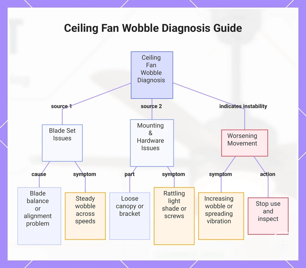
Wobble and vibration in a ceiling fan with light should be assessed by severity, source, and whether the movement increases during operation. The key distinction is between minor, stable movement and wobble that becomes stronger, uneven, or spreads across components. Safety response depends on whether the movement remains consistent, worsens, or indicates loose parts during use.
Blade movement, canopy shifting, light shade rattle, and screw looseness each create different vibration patterns that help identify the source. Blade balance or blade alignment issues often appear as steady wobble across speeds. Canopy or bracket movement typically produces shaking near the ceiling mount. Light shade or screws may introduce intermittent vibration or rattling depending on speed and operating conditions. Diagnosis should focus on the affected part rather than assuming a single cause.
New installations, older ceiling fans, or wobble that only appears at higher speed settings can change interpretation of vibration behavior. Recently installed units may show temporary movement during settling, while older systems may develop loose parts over time. High-speed-only wobble can indicate stress that is not visible at lower settings. If movement increases or becomes unstable, inspection should be considered and continued use may need to be stopped.
Diagnostic checklist:
- Blade set → blade balance or blade alignment issue → visible wobble across speeds → monitor or inspect if worsening
- Canopy / bracket → loose parts at mounting point → vibration near ceiling area → inspection required
- Light shade / screws → rattle or vibration noise → movement changes with speed → check for loose hardware
- Worsening movement → increasing wobble or spreading vibration → indicates instability → stop-use and inspection
This chart shows how to assess wobble and vibration in a ceiling fan by identifying the source, movement pattern, and required safety action.
Blade balance and alignment problems
Blade balance and blade alignment problems can cause wobble in a ceiling fan with light, but they are not the only possible cause of vibration. Blade balance issues or blade alignment changes in the blade arm may lead to uneven movement, yet other structural or loose-part conditions can produce similar wobble patterns. This means blade-related checks must be treated as one diagnostic layer rather than a complete explanation, and structural inspection boundaries still apply when symptoms persist.
Warped blade conditions, damaged blade surfaces, or uneven blade alignment can disrupt blade balance and create vibration that changes with speed. A balancing kit may help reduce visible wobble during a correction attempt, but it does not confirm the issue is limited to blades. When persistent wobble continues after balancing or alignment checks, it may indicate deeper mounting or structural concerns, and persistent wobble should be treated as an inspection signal.
Diagnostic checklist:
- Blade damage → warped blade or physical defect → uneven rotation pattern
- Blade alignment → blade arm misalignment or uneven blade set → movement imbalance
- Balancing kit attempt → correction applied → limited or no improvement
- Persistent wobble → wobble continues after adjustments → inspection required signal
Loose canopy, shade, screw, and bracket signs
Loose visible parts such as the canopy, shade, screws, and bracket can turn normal vibration into a safety concern in a ceiling fan with light. These signs of looseness often appear as rattle, visible gap, or shifting during operation and should be checked before continued use. Ignoring these indicators may increase movement instability in the fan or light assembly over time. :contentReference[oaicite:0]{index=0}
When a rattle repeats, a canopy shows movement, or a shade becomes unstable, it often indicates developing looseness rather than normal operating noise. Screws backing out or a bracket shifting can change how vibration behaves during operation, especially at higher speeds. If these signs continue after initial observation, the condition may indicate progressive loosening that requires inspection rather than continued use.
Loose visible parts should be checked before continued use.
- Canopy → visible gap or movement → may indicate mounting looseness → inspection required
- Shade → rattle or instability → may indicate looseness → check condition before continued use
- Screws → missing or backing out → direct safety risk → stop-use condition
- Bracket → shifting or noise during operation → possible structural looseness → inspection required
Unsafe signs that need professional inspection
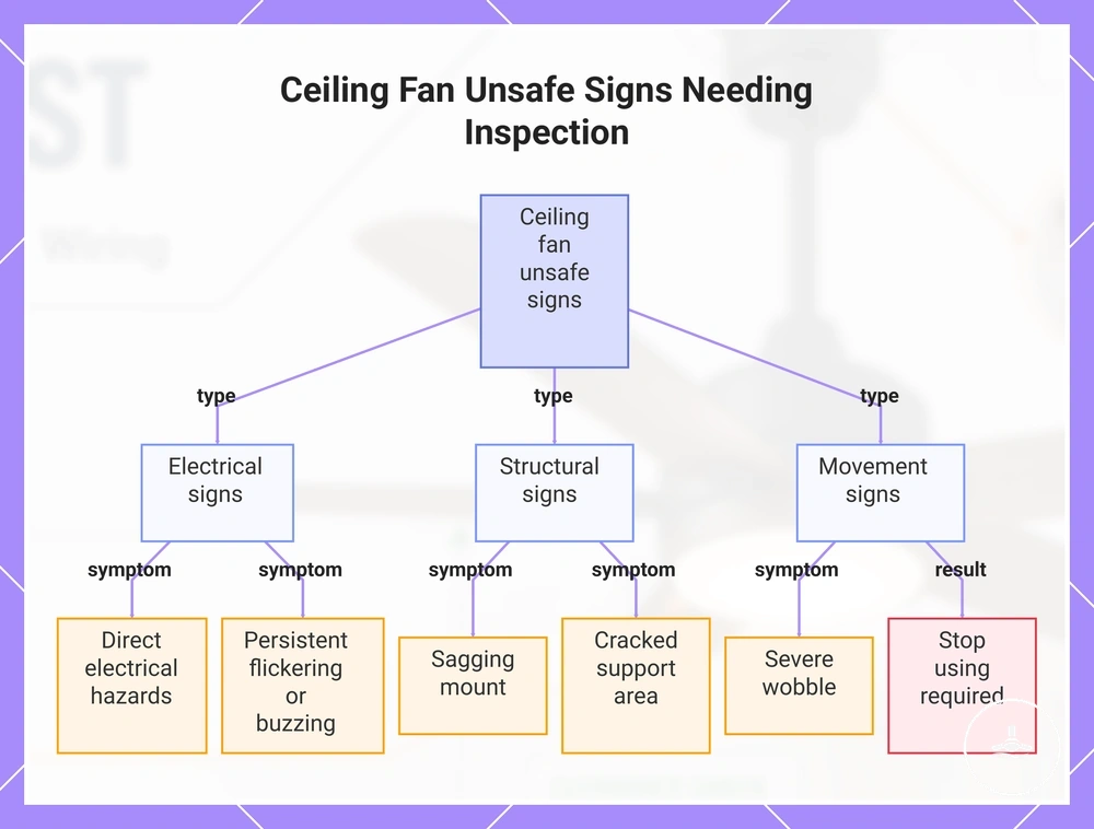
Unsafe signs that need professional inspection include physical, electrical, and movement-related indicators that should move a ceiling fan with light from normal checklist use to stop using or qualified inspection. These signs often appear together and suggest the system is operating outside safe boundary conditions, requiring escalation rather than continued monitoring. In most cases, the appropriate response is either to stop using or seek professional inspection depending on severity.
Burning smell, visible sparks, breaker trips, exposed wiring, severe wobble, sagging mount, and cracked support area are key warning signals that should not be treated as routine variation. These conditions indicate a mix of electrical and structural risk, and they must be evaluated against installation limits to determine whether the setup remains within safe operating boundaries. In such cases, continued use should be reconsidered and professional inspection becomes the safer direction.
When flickering or buzzing persists, it may indicate ongoing electrical instability rather than temporary fluctuation. These symptoms can align with flickering light warning signs and should be treated as escalation signals if they continue across operating modes. If the condition does not improve or appears alongside other warning signs, stop using and qualified inspection is typically required.
Final warning checklist:
- Electrical signs → burning smell, visible sparks, breaker trips, exposed wiring → stop using and professional inspection
- Structural signs → sagging mount, cracked support area → potential mounting instability → professional inspection required
- Movement signs → severe wobble → unsafe operational instability → stop using
- Light-related signs → persistent flickering or buzzing → possible electrical instability → monitor or inspect depending on severity
This chart categorizes the main warning signs for ceiling fans with lights into electrical, structural, and movement indicators, along with the required response.